ROUTE COMMAND CENTRE
Introduction
The Route Command Centre is the home for all route placement editing and configuration options in Proteus. It can be launched from the Tools Menu or, more commonly, via the R keyboard shortcut. Importantly the keyboard shortcut can launch the dialogue form while in the middle of placing or editing a route meaning that you can make changes or adapt the routing modes at any time.
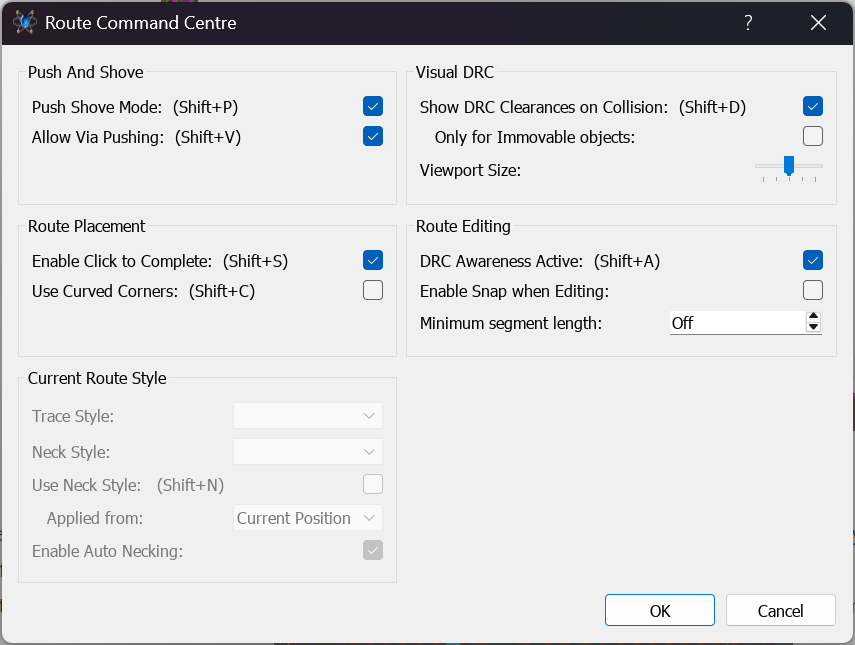
Route Command Centre Dialogue Form
Accelerators
All the main modes of operation have keyboard accelerators as shown on the dialogue form. It's well worth learning these as you can then make changes straight from the keyboard without needing to launch the Route Command Centre dialogue form at all.
The current shortcut for each option is appended to its label on the dialogue form, so the Push Shove Mode label reads "Push Shove Mode: (Shift+P)" while that mapping is in force. If you remap a command the label follows.
If you want to change the keyboard mappings to something that suits you better or you want to map some of the sub-modes you can do so via the Set Keyboard Mapping command on the System Menu.
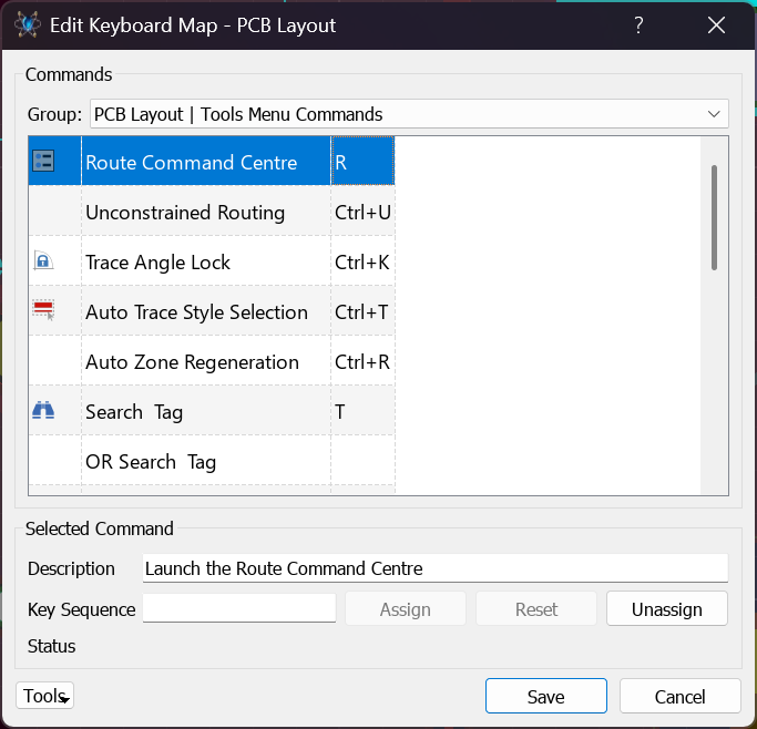
Route Command Centre commands can be mapped to keyboard shortcuts of your choice.
Here are the important accelerators in Route Command Centre.
| Keyboard | Action |
| R | Launches the Route Command Centre. |
| SHIFT+P | Toggles Push Mode on and off. Affects both route placement and route editing |
| SHIFT+D | Toggles Visual DRC view on and off. |
| SHIFT+A | Toggles Design Rule Aware Route Editing on and off. |
Notices
A notice appears at the top of the Route Placement section when the current state of the editor limits what the dialogue can do:
- Currently in Unconstrained Routing Mode (Tools Menu). Modify any Route Command Centre option to escape this mode.
- Currently using un-accelerated Graphics Mode. Route Pushing and Visual DRC features are unavailable in this Mode.
The second notice matters most. On un-accelerated graphics the push and Visual DRC options are present but have no effect, so if push mode appears to do nothing this is the first thing to check.
Status Bar
The current routing mode is displayed on the status bar along with other useful information about the current routing operation. This is particularly helpful when you are toggling configuration options with the keyboard because you can check on the status bar what the current operating mode is.
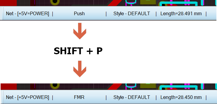
Status bar reflecting the switching of routing modes from Push mode to FMR mode.
Persistence
Route command centre settings tend to persist in the registry, except for the route styling which will always initialise from the net class defaults when you start route placement. In practise we expect a good deal of toggling using keyboard accelerators depending on the routing situation and the configuration can be changed dynamically at any time by launching the route command centre.
Two qualifications are worth knowing. The route styling is only taken from the net class while Auto Trace Style Selection is enabled; with it turned off the trace style comes from whatever is highlighted in the Object Selector instead. And the Route Command Centre settings are also written into layout templates, so a design started from a template inherits that template's routing configuration rather than your last session's.
You'll get some detailed information on each dialogue item from the context sensitive help. Click on the question mark at the top right of the dialogue form to launch.
Push And Shove
These commands toggle push mode on and off and apply to both route placement and route editing.
Push Shove Mode (SHIFT+P)
This is the main behavioural toggle, switching Push mode on and off.
- When push mode is on the track being placed or edited will move other tracks (and vias where selected) out of the way while maintaining design rule clearances.
- When push mode is off, route placement happens in FMR mode where you can hug other objects but not move them. Route editing is similarly unable to move other objects on the board.
Normally, you would toggle this option directly from the shortcut key with the current mode being shown on the status bar.

The status bar showing the current route placement mode.
Allow Via Pushing (SHIFT+V)
This allows the route being placed or edited to not only move tracks but also vias as well.
It's very useful but it can disturb routes on more than one layer and therefore require more tidy up. Generally speaking, it's best left on since most via pushes are small nudges.
Bear in mind that via pushing can slow things down a lot, particularly if you are nudging a group of closely positioned vias on a multi-layer board. The best thing you can do to mitigate this is left click to place an anchor as soon as you have moved the vias to a suitable position. Placing an anchor will commit the route so far (you can still unwind by moving the mouse back over the route) and all of those push calculations no longer need to be made on every mouse move as you continue with the rest of the route placement.
If you're trying to push a via and it's not moving it could be blocked by an immovable object on another layer.
If you turn off DRC Awareness (see below) then push editing will have no effect since the track being edited cannot 'see' any other objects to push them.
See Also:
Route Placement
These options are specific to route placement and apply regardless of whether Push mode is enabled or not.
Enable Click To Complete (SHIFT+S)
Click to Complete is a calculated solution to the destination shown as a 'shadow track' in front of the route being placed. You can complete the route at any time by pressing the ENTER key.
Notes:
- When you are pushing tracks Click to Complete will not attempt to find a solution.
- You may want to turn this option off if you have a very large and complex board and it is causing a performance overhead.
Use Curved Corners (SHIFT+C)
This switches the corner type from mitred to curved.
Curved cornering will typically work less well on dense boards, unless the curved routes are placed first.
You can also change the cornering type of individual tracks from the Mitring sub-menu on the track context menu, which offers Mitre and Unmitre, or for the whole board from the Mitre All Tracks on Layout and Unmitre All Tracks on Layout commands on the Edit menu. This will present an option to switch the cornering type between curved and linear.
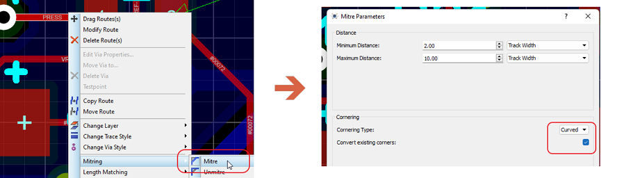
Switching the cornering type of a track between curved and linear from the Mitring sub-menu.
Current Route Style
The bottom left section of the Route Command Centre allows control of track width and neck width while in the middle of placing a route. These options will all be disabled unless you are in the middle of route placement so to use them you would.
- Start placing a route.
- Press R to launch the Route Command Centre
- Change route and neck width as needed
- Exit the dialogue form and continue route placement.
- Repeat at a later point in the route as needed.
Applied from
This combo decides how much of the route a style change affects. Current Position applies the new style from the point you have reached onward, leaving the segments already placed at their original width. Entire route re-applies the style to the whole of the route being placed, back to its start.
Enable Auto Necking
Auto Track Necking (ATN) automatically narrows the track to the net class neck style when it needs to squeeze between obstacles, then returns it to the full width once clear. This checkbox is the control for it, and like the rest of this group it is only enabled while a route is being placed.
By default no neck style is set on a net class, so auto necking has no effect until you choose one in the Design Rule Manager on the Technology menu. Set both the neck style and, if the board needs it, the inner layer neck style for each class you intend to neck.
By far the most common use of these options will be to toggle necking mode on and off as you route a track in and out of a dense area. You don't need to go into Route Command Centre to do this. The SHIFT+N shortcut key will toggle neck style on and off and the status bar will update to show both when you are in neck style mode and also the length of the current neck routing.
Route Styles come from the Net Class as set in the Design Rule Manager. The overrides here allow in route modification but are not intended to be a substitute for setting up net classes properly.
Route Editing
The route editing options are primarily concerned with design rule awareness. By default, track editing operations are design rule aware. This is almost always what you want to happen and will make tidying up the PCB a much easier job. However, sometimes you just want to get things out of the way and are prepared to deal with violations at a later point. If this is the case you can turn the DRC awareness off completely.
DRC awareness needs to be turned on in order to push other routes when editing. If DRC awareness is off there are no obstacles and you can edit into an illegal position.
Consider the example below. Here there is no legal edit to be made because our violation is at the component pins. A design rule room needs placing with specific clearances for the IC area but we may want to edit tracks in the meantime. We can't do this with DRC aware editing on because there is no legal solution to the edit, so the process has to be SHIFT+A to turn off, edit as needed and then SHIFT+A to toggle back on when we're finished.
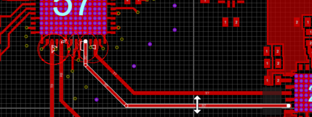
No track edit will result in a DRC legal position so turn DRC aware editing off.
SHIFT+A is the DRC Aware Editing toggle. Do not use CTRL+A, which is the Align Objects command and will realign every tagged object on the board.
When editing with DRC awareness off it's a really good idea to have Visual DRC turned on. This will both show you where nearby clearances are and also indicate when the route is in violation.
Meanwhile, the snap setting will constrain editing to the current snap. This is not normally a good idea as it will reduce the number of valid positions for the object being moved and of course will not play terribly well with DRC awareness. However, it may occasionally be helpful in boards where all of the IC's share the same pin pitch.
Finally the minimum segment size provides a way to prevent tiny sliver segments of routes and will restrict the smallest segment of track allowed. This is generally ok but there are times when it causes subtle problems (nearly vertical track between two pads for example) with editing.
Visual DRC
Visual DRC provides a viewport around the mouse and each object shows an expansion corresponding to its design rule clearance in an overlay. This instantly lets you see whether the route being placed or edited can move where you want it to go and then take action such as toggling push mode or changing track style to squeeze through a tight gap.
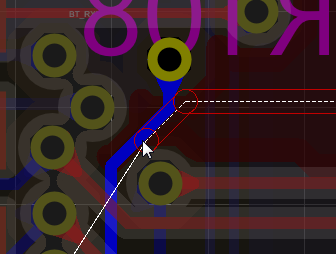
Visual DRC Auras around Tracks and Vias when placing a route.
You can choose whether only immovable objects or all objects should contribute their DRC 'auras' to the viewport area. Immovable objects are of course every object when in FMR mode but exclude tracks (and most often vias as well) when in push mode. You can also adjust the size of the viewport using the slider options. A large viewport on a dense board may impact performance slightly.
Visual DRC during Editing
If you are editing with DRC awareness on then the Visual DRC display will be exactly the same as during placement, showing you the clearances of nearby objects. However, when you turn DRC aware editing off (e.g. because the track is already in violation) Visual DRC gains two additional capabilities.
Track in Violation
The border of the Visual DRC viewport will highlight whenever any part of the route is in violation. This is an important indicator, particularly on large routes where the route segment in violation may not be the one you are editing or where editing brings the route into violation somewhere outside the screen area.
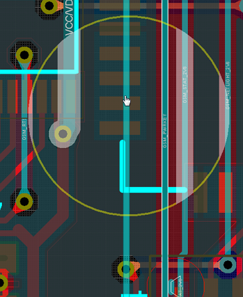
Viewport border colour indicates a violation somewhere on the route (via below).
Viewport Track in Violation
Trace segments and objects which are in DRC violation with the currently edited route inside the viewport will be highlighted. This allows for fine control during editing, allowing you to zoom in and carefully position the route without creating a DRC error.
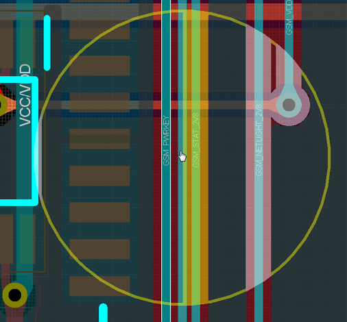
Violation inside the viewport area is highlighted as well.
Make sure you do not have snap to grid on when attempting fine control editing operations.
Note
Visual DRC is a guidance for route placement and it is possible in some narrow circumstances to route inside the clearance 'shroud'. Consider the case below:
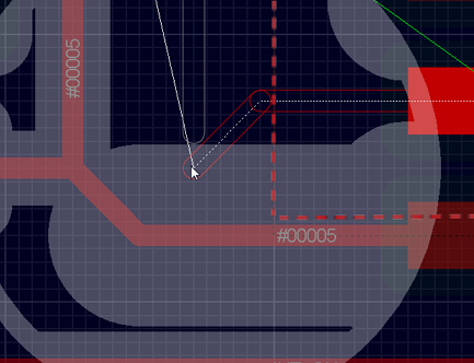
Net #00005 has vDRC clearance from the Room rule until the tertiary junction.
Here the pad connected to net #00005 is partially inside a DRC room with a large clearance. For performance reasons the vDRC clearance shroud covers the entire segment of track, even though the actual clearance changes as we exit the design rule room. This means that, as shown above, it is possible to move inside the shroud in that segment area outside the room. This is unlikely to happen but possible and therefore worth mentioning. The route will stop (or push) at the actual pad->trace clearance at the point of intersection. It is only the DRC Visual which may not be up to date on a route segment that traverses a design rule room. The live DRC system, violations and clearances are unaffected.